Key:
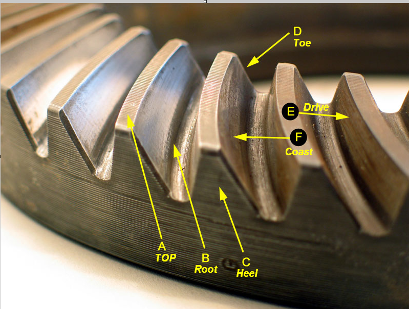
A – Top. The top of the gear tooth, a.k.a. Face, Top Land / górna część zęba koła zębatego
B – Root. The bottom of the gear tooth, a.k.a. Flank / spód zeba przekładni
C – Heel. The outside-diameter-end of the gear tooth / Zewnętrzna średnica koła zębatego
D – Toe. The inside-diameter-end of the gear tooth / Wewnętrzna średnica koła zębatego
E – Drive. The convex side of the gear tooth* / Wypukła strona zęba koła
F – Coast. The concave side of the gear tooth* / wklęsła strona zęba koła
Grubość podkładek bocznych (fabryczne ustawianie mostu)
Preload łożysk bocznych suma podkładek w wolnej przestrzeni + 0,015″ >>> 0,381mm
The differential side bearing preload adjustment must be completed before the backlash adjustment can be started.
Regulacja napięcia wstępnego bocznych łożysk układu różnicowego musi być zakończone przed rozpoczęciem można regulacji luzu międzyzębnego.
In order to maintain the original backlash, adjust the differential case side bearing preload by changing the thickness of the left and the right side shim packs equally.
W celu zachowania oryginalnego luz miedzyzbębnego ,wyregulować kosz układu różnicowego napięciem wstępnym łożyska bocznego poprzez zmianę grubości podkładek po lewej i prawej stronie podobnie.
Measure the service shims and the spacers one at a time. Add the measurements together in order to obtain the total thickness of the left or the right side shim pack.
Zmierz podkładki regulacyjne, elementy dystansowe i serwisowe razem. Dodanie pomiarów razem ze sobą pozwoli na uzyskanie całkowitej grubości zestawu podkładek z lewej lub prawej strony.
Do not use or reuse the original cast iron production shims. Use service shims and spacers instead.
Nie używaj do ustawiania i ponownego wykorzystania podkładek oryginalnych żeliwnych. Użyj nowych podkładek i dystansów serwisowych.
- Install the drive pinion, if necessary.
Zamontować koło zębate napędu, jeśli to konieczne.
- Measure the rotating torque of the drive pinion using an inch-pound torque wrench. Specification The rotating torque of the drive pinion should be 1.7 – 3.4 Nm (15 – 30 inch lbs.) for new bearings or 1.1 – 2.3 Nm (110 – 20 inch lbs.) for used bearings.
Dokonaj pomiaru momentu obrotowego zębnika napędowego przy użyciu klucza dynamometrycznego wg specyfikacji:
Moment obrotowy zębnika napędowego powinna być w przedziale:
1,7 – 3,4 Nm (15 – 30 inch lbs.) dla nowych łożysk lub
1,1 – 2,3 nm (110 – 20 inch lbs.) łożysk używanych.
Zapisz wartość dokonanego pomiaru.
Important: Before installation of the differential assembly, ensure that the differential side bearing surfaces in the axle housing are clean and free of burrs. If the original differential side bearings are to be reused, the original differential side bearing cups must also be used.
Ważne: Przed montażem zespołu mechanizmu różnicowego, upewnij się, że boczne powierzchnie korpusu mostu i łożyska w obudowie osi są czyste i bez zadziorów. Jeśli łożyska boczne dyferencjału mają być ponownie wykorzystane, należy użyć tych samych pierścieni zewnętrzne.
- If the rotating torque for the drive pinion bearings is not within specifications, adjust as necessary. Refer to Drive Pinion and Ring Gear Replacement.
Jeżeli moment obracający dla łożysk zębnika napędu nie jest zgodny ze specyfikacją należy dokonać regulacji w razie potrzeby (Patrz wymiana zębnika i pierścienia zębatego)
- Install the differential assembly with the differential side bearings and differential sidebearing cups into the axle housing.
Zamontować zespół mechanizmu różnicowego z łożyskami bocznymi i pierścieniami zewnętrznymi w obudowie mostu.
- Insert one 4.318 mm (0.170 inch) thick service spacer into the left side of the axle housing
Włożyć jedną podkładkę serwisową 4,318 mm (0,170 cala) po lewej stronie obudowy most.
- Side the differential assembly towards the service spacer in order to hold the spacer in place.
Przesunąć kosz układu różnicowego w stronę podkładki serwisowej w celu jej przytrzymania na miejscu.
- Install the J22779 between the right side differential side bearing cup and the axle housing.
Important: Over-tightening may spread the housing and result in incorrect shim selection.
Zamontuj sprawdzian (J22779) pomiędzy prawym zewnętrznym pierścieniem łożyska, a obudowa mostu. Ważne: Nadmierne dokręcenie śruby ustawiaka, może rozeprzeć obudowę mostu i skutkować nieprawidłowym doborem podkładek.
- Tighten the knob on the J22779 until there is moderate drag when the J22779 is moved.\
Dokręcić śrubę w sprawdzianie (J22770) do momentu umiarkowanego opru.
- Remove the J22779.
Wyjąć sprawdzian (J22770)
- Remove the service spacer.
Wyjąć podkładkę serwisową (4,318 mm (0,170 cala))
- Using a micrometer, measure the thickness of the J22779 in 3 locations.
Za pomocą mikrometru zmierzyć grubość sprawdzianu (J22770) w 3 punktach.
- Calculate the average of the 3 measurements. Record the measurement.
Obliczyć średnia z 3 pomiarów i zapisać wynik.
- Add the thickness of the service spacer, measured in step 11 to the average thickness of the J 22779 , measured in step 12. The resulting value is the total service shim thickness without preload for the axle.
Dodać grubość podkładki serwisowej zmierzonej w punkcie 11 do średniej wyliczonej w punkcie 12. Uzyskana wartość oznacza całkowitą grubość podkładek eksploatacyjnych bez napięcia wstępnego łożysk.
- Insert one BENT 1.016 mm (0.040 in) service shim between the right side differential side bearing cup and the axle housing. The service shim must be installed between the service spacer and the differential side bearing cup.
Wsadzić jedna podkładkę kalibracyjną 1,016mm (0,040 cala) Pomiędzy prawe łożysko a obudowę osi. Podkładka musi być zainstalowana między podkładką serwisową a bieżnią łożyska.
- Install the J 22779 into the left side of the axle housing. The J 22779 must be installed between the service spacer and the differential side bearing cup.
Zamontować J22779 po lewej stronie obudowy kosza, J22779 musi być zainstalowany między podkładka serwisową a bieżnią kosza różnicowego.
- While rotating the ring gear back and forth, tighten the knob on the J 22779 until there is approximately 0.025-0.051 mm (0.001-0.002 in) of backlash between the ring gear and the drive pinion.
Obracając kołem koronowym tam i z powrotem dokręcić pokrętło ustawiaka J22779 dopóki luz między zębami nie będzie wynosił 0.025-0.051mm
- Once the correct amount of backlash is obtained, remove the J 22779.
Jeżeli luz będzie odpowiedni wyjmij ustawiak J22779.
- Remove the differential assembly with the differential side bearings and the differential side bearing cups.
Wyjmij układ różnicowy wraz z łożyskami bocznymi oraz kadłubkami mocującymi
- Remove the BENT service shim.
Wyjąć podkładki serwisowe
- Using a micrometer, measure the thickness of the J 22779 in 3 locations. Calculate the average of the 3 measurements. This value is the left side service shim thickness without preload.
Korzystając z mikrometru zmierzyć ustawiak J22779 w 3 lokalizacjach. Obliczyć średnią z 3 pomiarów. Wartość ta jest lewa boczną grubością podkładek serwisowych bez napięcia wstępnego.
- In order to determine the right side service shim thickness, subtract the service shim thickness for the left side of the axle, calculated in step 20, from the total service shim thickness, calculated in step 13. This value is the service shim thickness for the right side of the axle without preload.
W celu określenia właściwej grubości podkładek serwisowych odjąć grubość podkładek z lewej strony obliczoną w kroku 20. Wartość ta jest grubością podkładek serwisowych po prawej stronie osi bez naprężenia wstępnego.
- In order to preload of the differential side bearings and set the backlash to approximately 0.127-0.223 mm (0.005-0.009 in), take the value determined in step 21 and add 0.203 mm (0.008 in) service shim thickness to this amount.
W celu wstępnego obciążenia łożysk układu różnicowego ustawić luz około 0.127-0.223 mm, przyjąć wartość 21 i dodać podkładkę serwisową o grubości 0,203mm do wysokości podkładek.
- Assemble the left side shim pack using one 4.318 mm (0.170 in) service spacer and the appropriate amount of service shims equaling the thickness determined in step 20. Measure the service spacer and the service shims separately. Add the measurements together in order to determine the total
Zamienić pakiet lewych bocznych podkładek na jedną 4.318mm i odpowiednią ilość podkładek serwisowych równej grubości określonej w kroku 20. Zmierzyć dystanse i podkładki serwisowe razem w celu określenia grubości całkowitej.


